Setting up GLM3 load management
In this entry, we explain how you can set up GLM3 load management.
Create a location
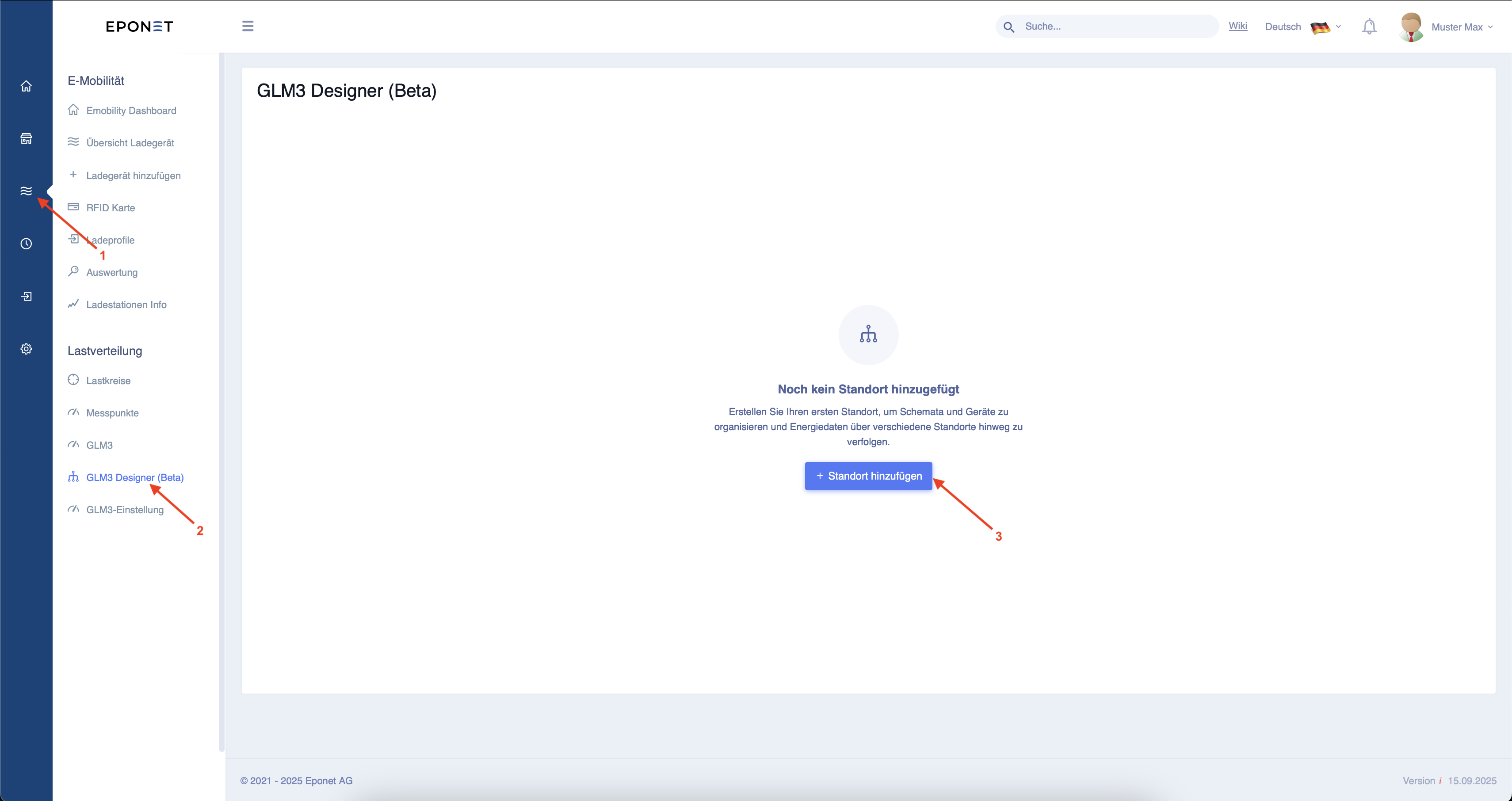
First, follow the three arrows on the Eponet portal to create a new location.
After clicking on "Add location", a window will open. Fill in the relevant fields, whereby the location name and description can be freely assigned. The MAC address must correspond to that of the EdgeServer installed at this location.
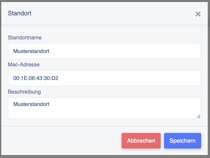
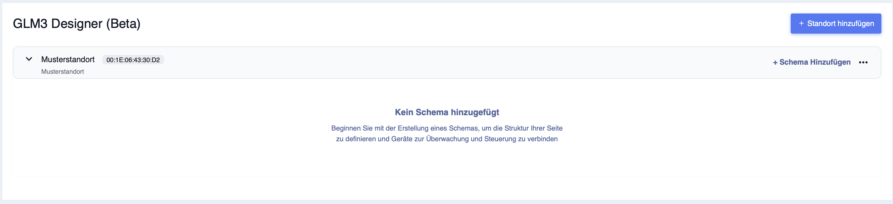
After clicking on "Save", the window closes again and you can see the location you have created.
Create schema
Now press "Add scheme" to configure the other settings.
You will now see the following window. Clicking on "Measuring point" allows you to set this on the right-hand side of the screen.
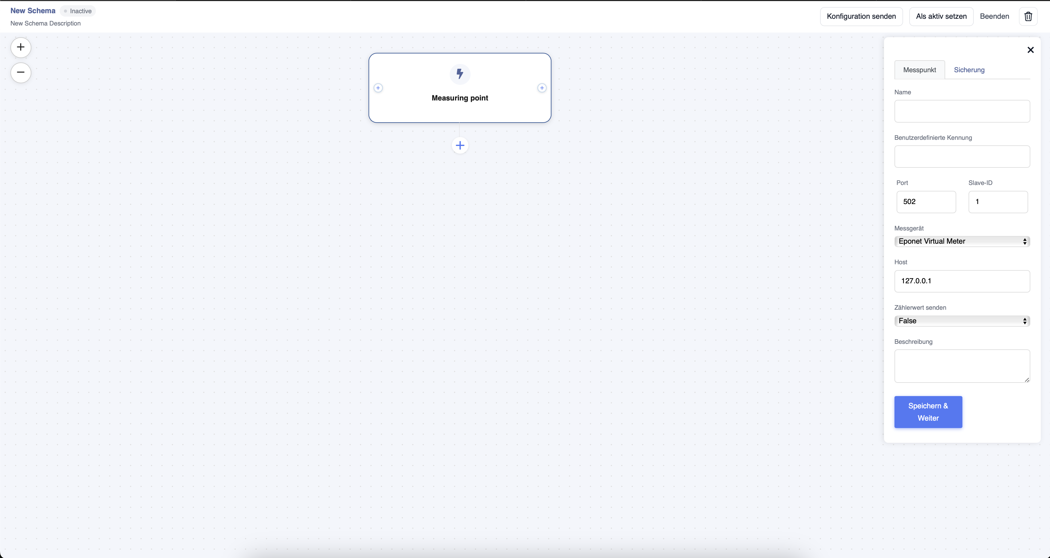
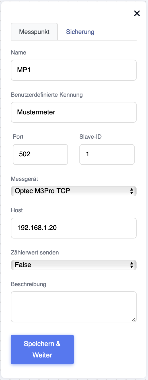
The name and user-defined ID can be freely assigned and are for overview purposes only.
Under "Measuring device", you can select the meter installed in the project from all meters implemented in Eponet.
The port, slave ID and host (IP address) are taken from the meter.
Under "Send meter value", you can select whether the meter should only be used for load management (False) or whether it should also be used as a meter for evaluation (True).
Once all fields have been set, you can confirm this by clicking on "Save & Continue".
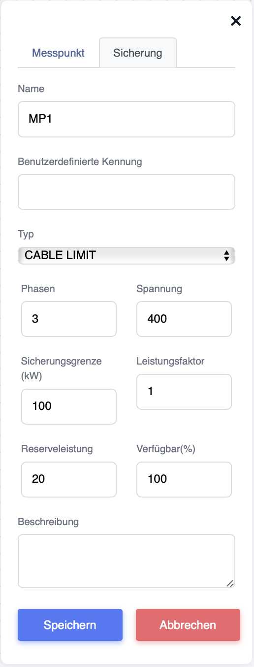
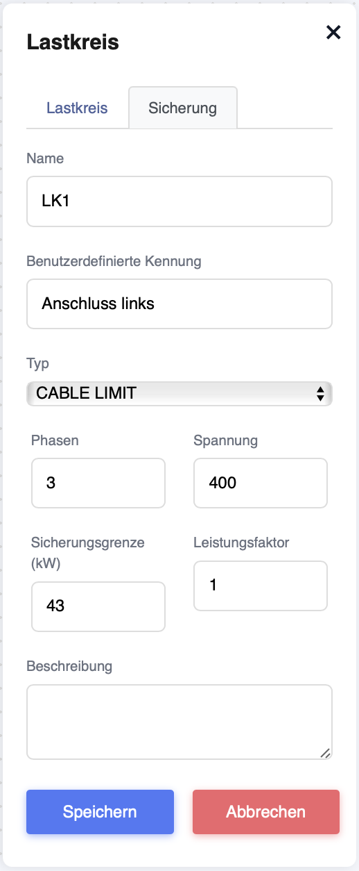
Now the fuse must be set.
Name: Can be freely selected
User-defined ID: Can be freely selected (not a mandatory field)
Type: This can be "Cable Limit" (serves as a limit for the cable cross-section) or "Digital" if it is a fuse that limits the power.
Phases: If it is a transformer measurement, this must be set to "1". For a normal measurement, there are "3" phases.
Voltage: How many volts are present on the system.
Fuse limit (kW): This is the maximum limit that load management must not exceed.
Power factor: Is determined by the installation.
Reserve power: The value set here is deducted from the maximum power (fuse limit). This allows you to absorb short-term voltage peaks.
Available (%): Here you can set how much % of the "fuse limit" should be used for load management.
Description: Here you can enter a text of your choice (optional).
Then confirm the settings with "Save".
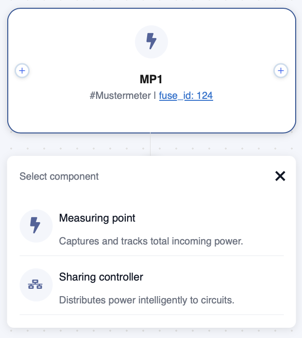
Now click on the + below the measuring point to add further components.
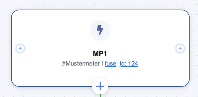
Select "Measuring point" to create an additional measuring point or "Sharing controller", which then controls the other components.
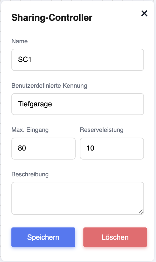
Once you have created a "Sharing controller", you can configure it as you did for the measuring point.
Name: Can be freely selected
User-defined identifier: Can be freely assigned and is used for better allocation (not a mandatory field)
Max. input: The input power from the measuring points can be set here. This is then the maximum power that may be passed on to the load circuits.
Reserve power: The value set here is deducted from the maximum power (safety limit). This allows you to absorb short-term voltage peaks.
Description: You can enter a text of your choice here (optional).
Then confirm the settings with "Save".
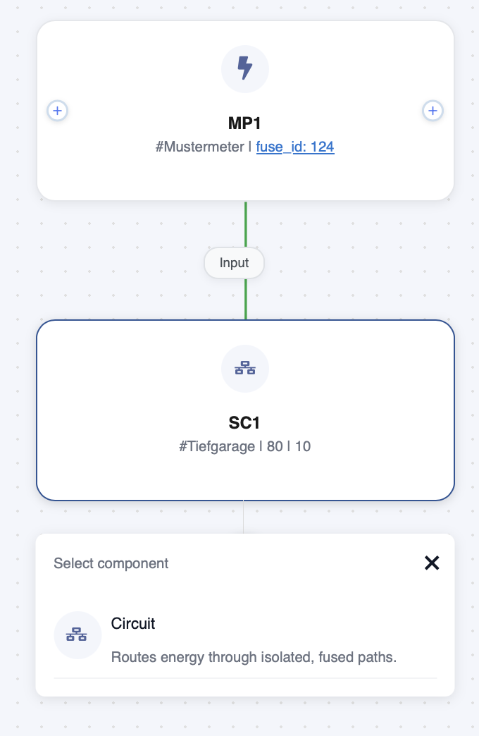
Now add a "Circuit" using the + on the sharing controller.
Once you have created a "load circuit", you can configure it as before with the sharing controller.
Name: Can be freely selected
User-defined ID: Can be freely assigned and is used for better allocation (not a mandatory field)
Priority: The priority of the load circuits can be set here. If it happens that not all charging stations can be supplied with a minimum amount of electricity, this setting determines which load circuit will be the first to have its electricity supply cut off. This is done in descending order (for example, first priority 3, then priority 2, and so on).
Description: You can enter any text you like here (optional).
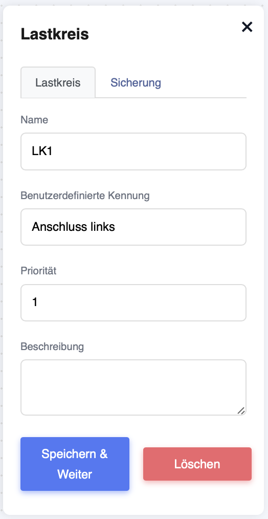
Now confirm the settings with "Save & Continue". You will then be redirected to the next settings page.
Name: Can be freely selected
. User-defined identifier: Can be freely assigned and is used for better allocation (not a mandatory field).
Type: This can be "Cable Limit" (serves as a limitation of the cable cross-section) or "Digital" if it is a fuse that limits the power.
Phases: If it is a transformer measurement, this must be set to "1". For a normal measurement, there are "3" phases.
Voltage: How many volts are available on the system.
Fuse limit (kW): This is the maximum limit that load management must not exceed.
Power factor: Is determined by the installation.
Description: You can enter any text here (optional).
Now confirm the settings with "Save".
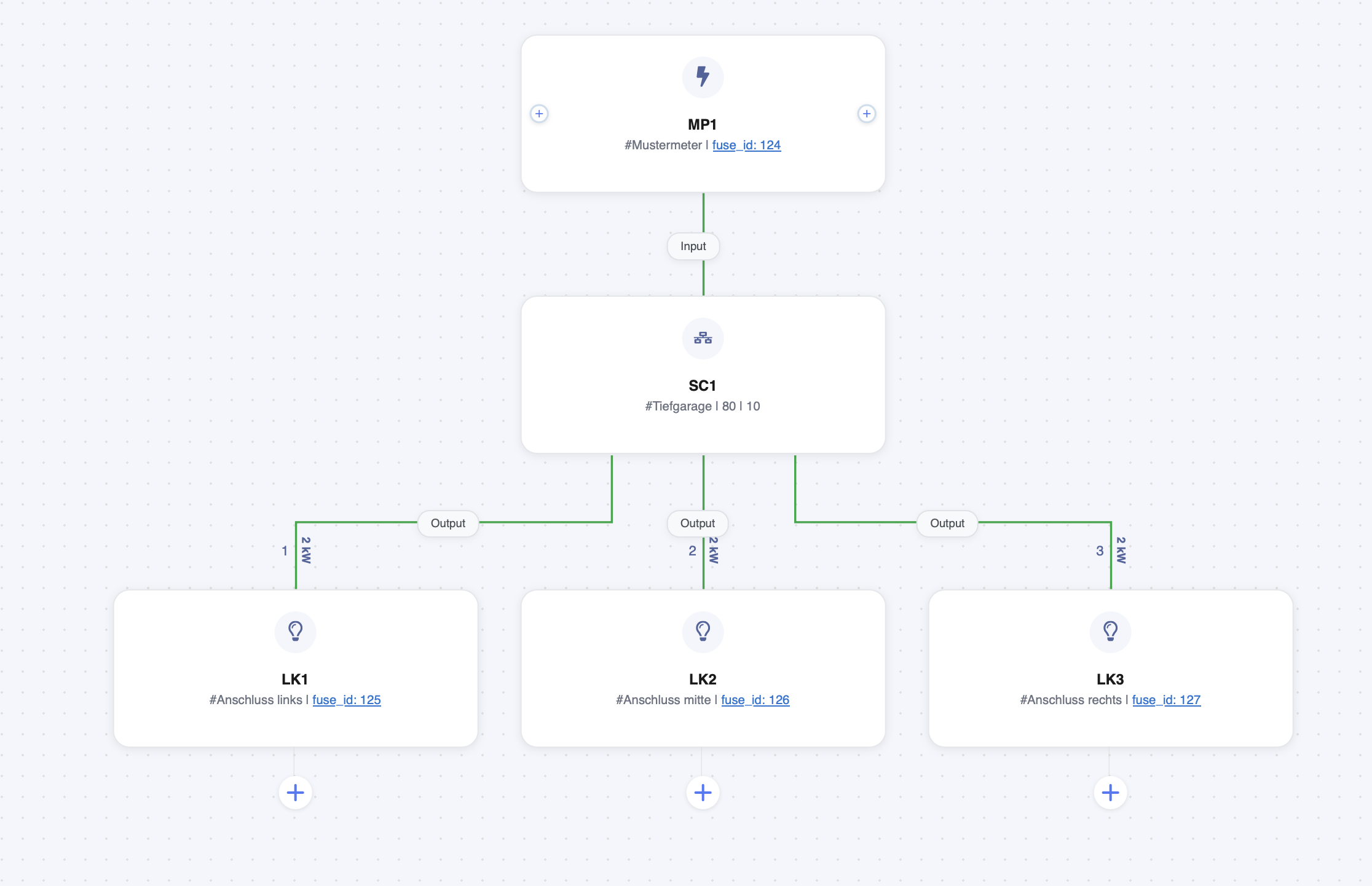
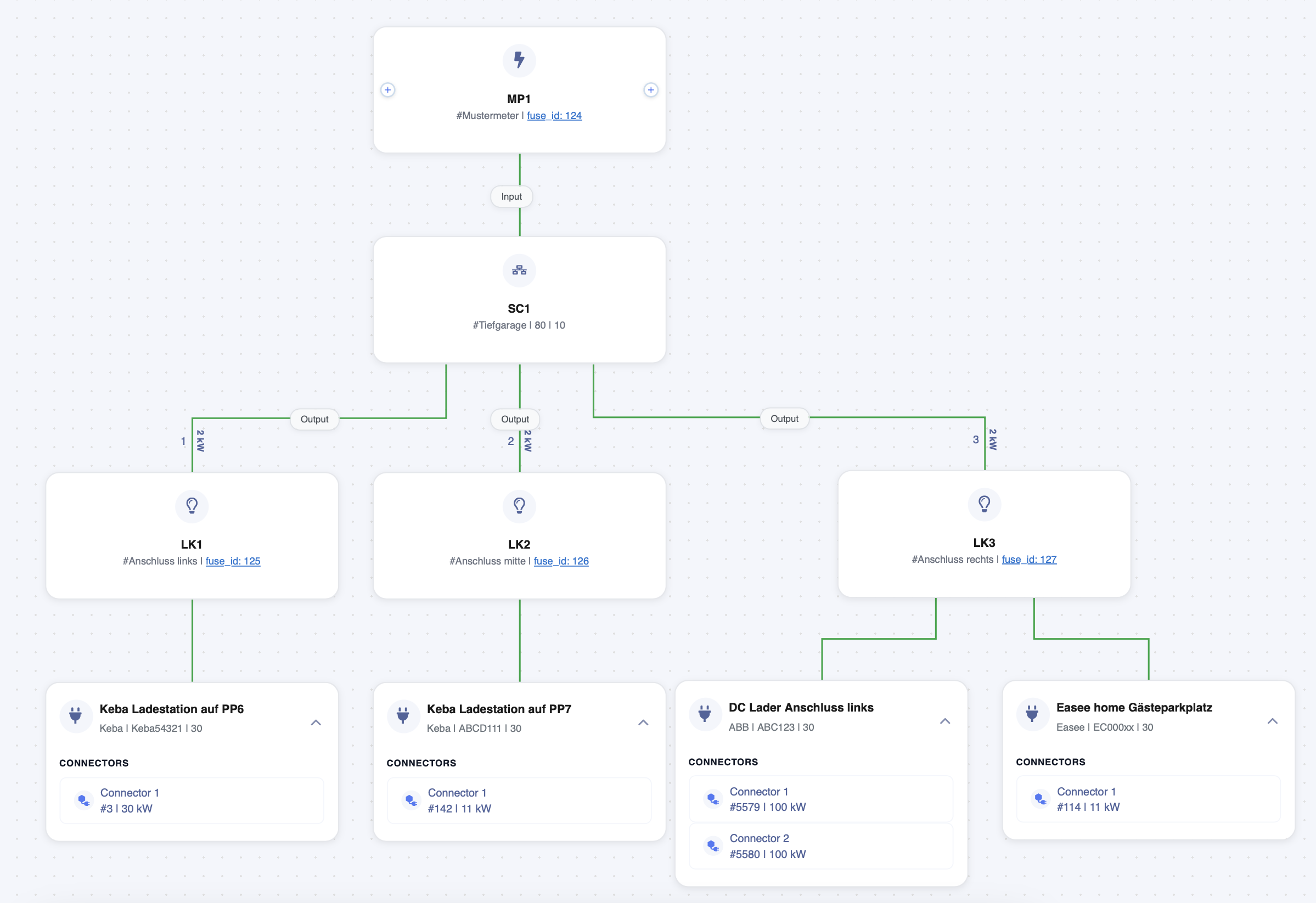
You can also create multiple load circuits as described above. Your
diagram could then look something like this.
Now add a "Charger" to the load circuit using the +.
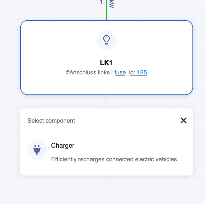
Here you can now select a charging station that you have previously created under "Charger".
Priority: Here you can set the priority of the charging stations. If it happens that not all charging stations can be supplied with a minimum amount of power, this setting determines which charging station in this load circuit will be the first to have its power supply cut off. This is done in descending order (for example, first priority 3, then priority 2, and so on).
Control method: Here you can set whether the charging station should be controlled in W or A. The preferred setting here is always W. Power
update interval: This value defines how often the power at the station that may be used for charging should be readjusted. The default here is 30 seconds for an AC charging station and 10 seconds for a DC charging station.
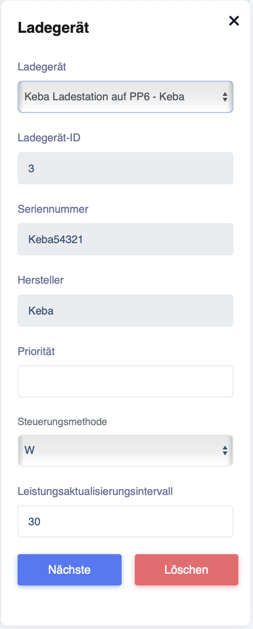
Now confirm the settings with "Next".
Now click on "Add more" under "Configure GPIO settings".
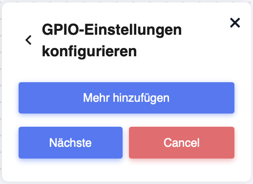
After clicking on "Add more", the window expands.
Here you can set the load shedding.
PIN number: With the PIN number, you can set which pin should be used for this charging station.
Set limit: This value describes the power to which the load shedding should be reduced when triggered (in W).
Inverted: If set to "False", load shedding is activated when there is a connection between GND and the connected pin. If this value is set to True, load shedding is triggered when there is no connection between GND and the pin.
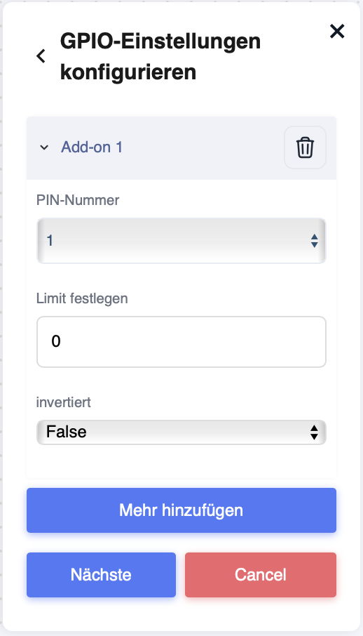
Now confirm the settings with "Next".
In the window that now opens, you can activate the charging station connections.
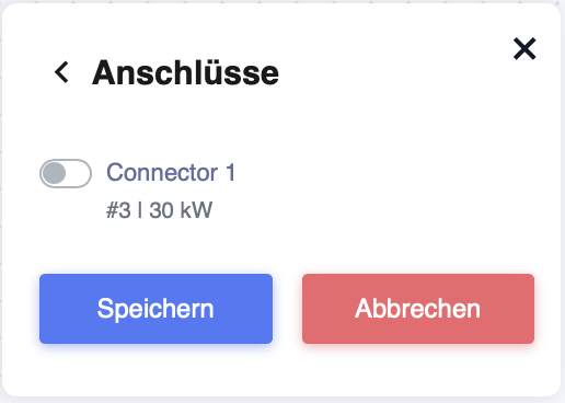
If the charging station has multiple connections, you can select the required ones here.
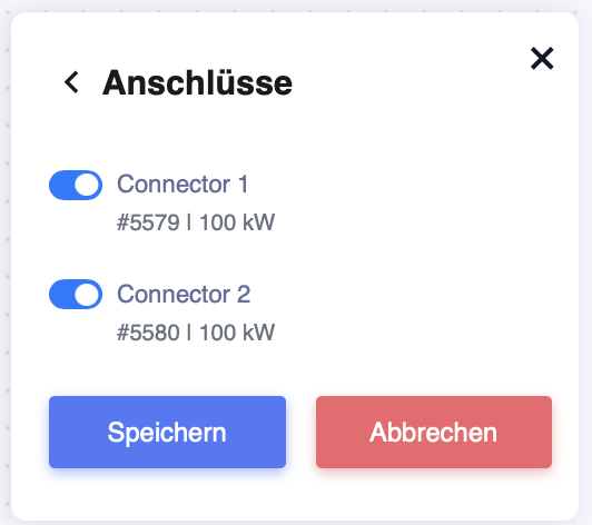
Then click on "Save".
Your diagram could now look like this.
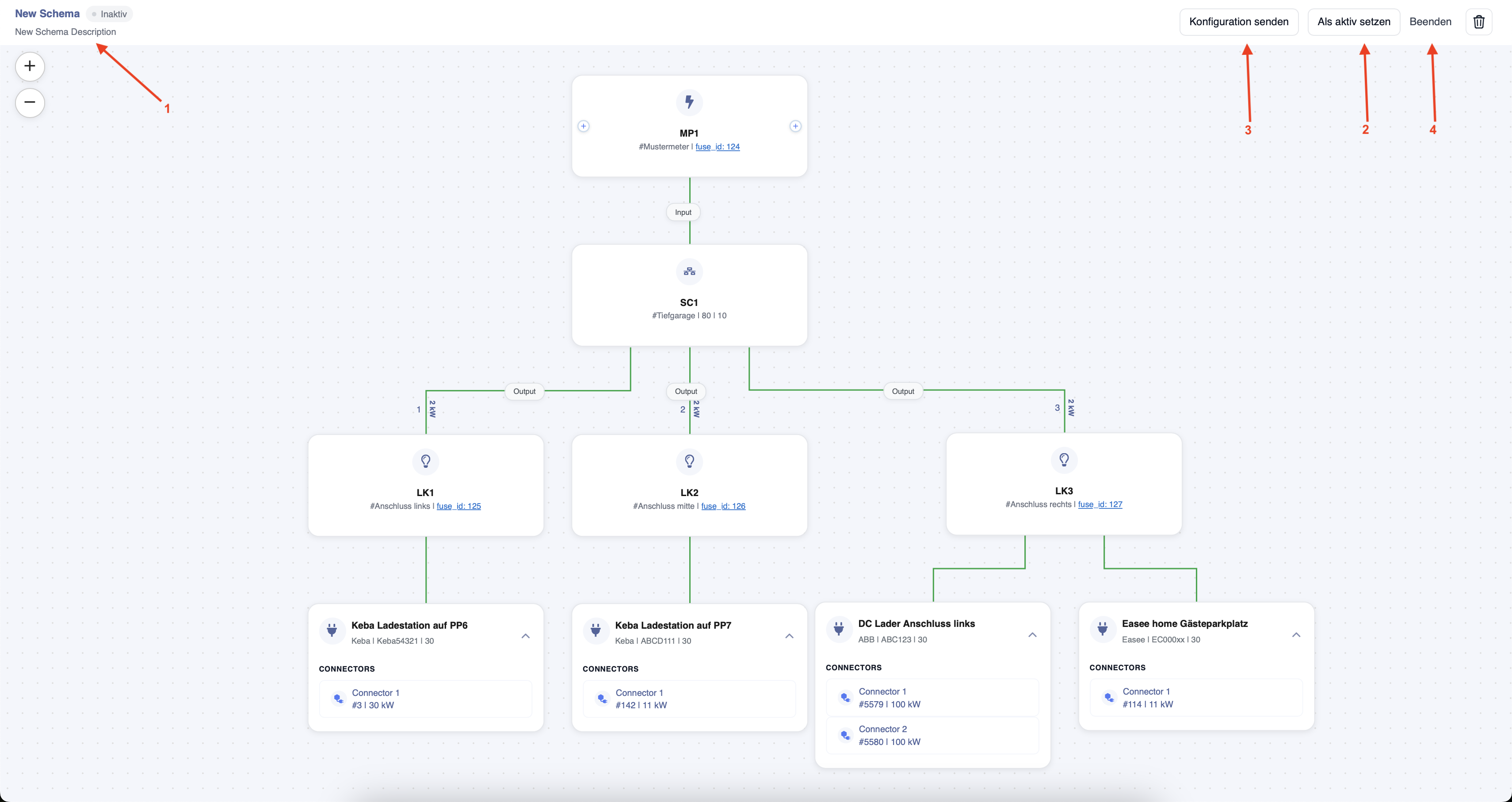
You can now complete the diagram.
Arrow 1: Here you can name the scheme by clicking on "New Scheme Description".
Arrow 2: If everything is set correctly, you can now set the scheme to "Active". If this is not done, the schema will not run on the EdgeServer.
Arrow 3: If you make a change to this schema afterwards, you must send it to the EdgeServer by clicking on "Send Configuration" to make the change active immediately.
Arrow 4: This takes you back to the original page.
Only one schema can be active on each EdgeServer at a time.
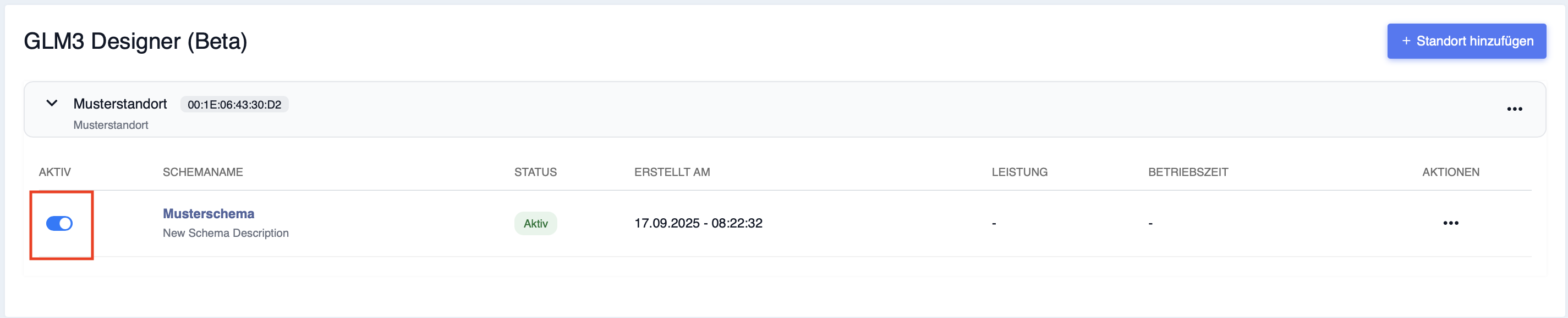
Now you can see that the schema is active, marked in red here.